
737-3/500 Pneumatics Panel
|
General
The
pneumatic system can be supplied by engines, APU or a ground source. The
manifold is normally split by the isolation valve. With the isolation valve
switch in AUTO, the isolation valve will only open when an engine bleed air or
pack switch is selected OFF.
Air for engine starting, air conditioning packs, wing
anti-ice and the hydraulic reservoirs comes from their respective ducts.
Air for pressurisation of the water tank and the aspirated TAT probe
come from the left
pneumatic duct. External air for engine starting feeds into the right pneumatic
duct. Ground conditioned air feeds directly into the mix manifold.
The minimum pneumatic duct pressure (with anti-ice
off) for normal operation is 18psi.
If engine bleed air temperature or pressure exceed limits,
the BLEED TRIP OFF light will illuminate and the bleed valve will close. You may
use the TRIP RESET switch after a short cooling period. If the BLEED TRIP OFF
light does not extinguish, it may be due to an overpressure condition.
Bleed trip off's are most common on full thrust, bleeds off, take-off's.
The reason is excessive leakage past the closed hi stage valve butterfly
which leads to a pressure build up at the downstream port on the
overpressure switch within the hi stage regulator. The simple in-flight
fix is to reduce duct pressure by selecting CLB-2 and/or using
engine and/or wing anti-ice.
WING-BODY OVERHEAT indicates a leak in the corresponding
bleed air duct. This is particularly serious if the leak is in the left hand
side, as this includes the ducting to the APU. The wing-body overheat circuits
may be tested by pressing the OVHT TEST switch; both wing-body overheat lights
should illuminate after a minimum of 5 seconds. This test is part of the daily
inspection.
|

737-400 Pneumatics Panel
|
Differences1/200's - The PACK switches are simply OFF/ON, rather than OFF/AUTO/HIGH on all other series.4/8/900's - Have two recirc fans for pax comfort and PACK warning lights instead of PACK TRIP OFF. See Air conditioning for an explanation. There are also two sidewall risers either side instead of one on all other series, this is why there appear to be two missing windows forward of the engine inlet. 
737-400 Sidewall risers
|
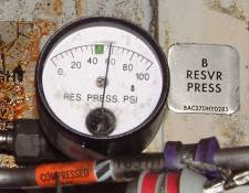 |
The hydraulic reservoirs are pressurised to ensure a positive flow of fluid reaches the pumps. A from the left manifold and B from the right. See wheel-well fwd. |
Schematic
Schematic courtesy of Derek Watts
|
|
Limitations
|
Max external air pressure: |
60 psig |
|
Max external air temp: |
450°F / 232°C |
| One pack may be inoperative provided maximum altitude is: | FL250 |
No comments:
Post a Comment