Warning Lights

Master Caution and System Annunciator
lights, left and right.
The Master Caution system was developed for the 737 to ease pilot workload as it was the first Boeing airliner to be produced without a flight engineer. In simple terms it is an attention getter that also directs the pilot toward the problem area concerned. The system annunciators (shown above) are arranged such that the cautions are in the same orientation as the overhead panel e.g. FUEL bottom left, DOORS bottom of third column, etc. On the ground, the master caution system will also tell you if the condition is dispatchable or if the QRH needs to be actioned. The FCOM gives the following guidance on master caution illuminations on the ground: Before engine start, use individual system lights to verify the system status. If an individual system light indicates an improper condition: Pressing the system annunciator will show any previously cancelled or single channel cautions. If a single channel caution is encountered, the QRH drill should not be actioned. Master caution lights and the system annunciator are powered from the battery bus and will illuminate when an amber caution light illuminates. Exceptions to this include a single centre fuel tank LOW PRESSURE light (requires both), REVERSER lights (requires 12 seconds) and INSTR SWITCH (inside normal FoV). When conducting a light test, during which the system will be inhibited, both bulbs of each caution light should be carefully checked. The caution lights are keyed to prevent them from being replaced incorrectly, but may be interchanged with others of the same caption. 
Keying of warning lights
|
||||||||||||||||||||||||||||||||||||||||||||||||||||||||||||||||||||||||||||||||||||||||||||||||||||||||||
Aural WarningsCockpit aural warnings include the fire bell, take-off configuration warning, cabin altitude, landing gear configuration warning, mach/airspeed overspeed, stall warning, GPWS and TCAS. External aural warnings are: The fire bell in the wheel well and the ground call horn in the nose wheel-well for an E & E bay overheat or IRS’s on DC. Only certain warnings can be silenced whilst the condition exists.To test the GPWS, ensure that the weather radar is on in TEST mode and displayed on the EHSI. Pressing SYS TEST quickly will give a short confidence test, pressing for 10 seconds will give a full vocabulary test. 
The GPWS pane.
Radio Altimeter CalloutsAutomatic rad-alt calls are a customer option on the 3-900 series. Calls can include any of the following:2500 ("Twenty Five Hundred" or "Radio Altimeter"). Noise LevelsIf is often commented how loud these callouts are. The volume level for these callouts and any other aural warnings is set so that they can still be audible at the highest ambient noise levels, this is considered to be when the aircraft is at Vmo (340kts) at 10,000ft.The design sound pressure level at 35,000ft, M0.74, cruise thrust is 87dB at the Captains seat, compared to 90-93dB in the cabin. Many pilots consider the 737 flightdeck to be generally loud. This is Boeings response to that charge: "Using the flight deck noise levels measured by Boeing Noise Engineering during a typical flight profile (entire flight), a daily A-weighted sound exposure was calculated using ISO/DIS 1999 standards. This calculation indicates the time weight noise exposure is below 80 db(A) and should not cause hearing damage. Flight deck noise improvement continues to be a part of current Boeing product quality improvement activities."And when asked later about the particularly noisy NG: "Boeing has conducted extensive flight tests to define the contributing noise sources for the 737 Flight Deck. Subsequently, various system and hardware modifications have been evaluated for possible improvements. Currently there are no proposed changes where the benefits are significant enough to warrant incorporation. Additional candidates are currently under study and if their merit is validated, they could be incorporated at a later date during production and retrofit."That said, in 2005 Boeing added 10 small vortex generators at the base of the windscreen which reduce flightdeck aerodynamic noise by 3dB. (See fuselage page for photo). |
||||||||||||||||||||||||||||||||||||||||||||||||||||||||||||||||||||||||||||||||||||||||||||||||||||||||||
Stall Warning Stall warning test requires AC power. Also, with no hydraulic pressure, the leading
edge flaps may droop enough to cause an asymmetry signal, resulting in a failure
of the stall warning system test. If this happens, switch the "B"
system electric pump ON to fully retract all flaps and then repeat the test.
Stall warning test requires AC power. Also, with no hydraulic pressure, the leading
edge flaps may droop enough to cause an asymmetry signal, resulting in a failure
of the stall warning system test. If this happens, switch the "B"
system electric pump ON to fully retract all flaps and then repeat the test.
System test switches on the aft overhead
panel
The OFF light may indicate either a failure of the heater of the angle of attack sensor a system signal failure or a power failure. The test disc should rotate, indicating electrical continuity, when the switch is held to the test position.  |
||||||||||||||||||||||||||||||||||||||||||||||||||||||||||||||||||||||||||||||||||||||||||||||||||||||||||
TCAS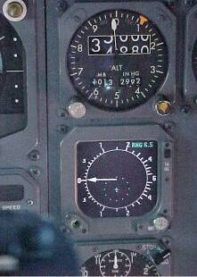  Various
versions of TCAS have been fitted to the 737 since its
introduction in the 1990's. The early days of TCAS there were
different methods of displaying the visuals. For the Honeywell system
(Previously AlliedSignal, previous to that -
Bendix/King), their most popular method for non-EFIS airplanes
was to install an
RA/VSI which was a mechanical VSI that had the "eyebrows" on the
outer
edge directing the pilot to climb (green) or stay away from
(red) and use the separate
Radar Indicator for the basic traffic display.
Even early EFIS aircraft had the RA/VSI (see photos left &
right) Various
versions of TCAS have been fitted to the 737 since its
introduction in the 1990's. The early days of TCAS there were
different methods of displaying the visuals. For the Honeywell system
(Previously AlliedSignal, previous to that -
Bendix/King), their most popular method for non-EFIS airplanes
was to install an
RA/VSI which was a mechanical VSI that had the "eyebrows" on the
outer
edge directing the pilot to climb (green) or stay away from
(red) and use the separate
Radar Indicator for the basic traffic display.
Even early EFIS aircraft had the RA/VSI (see photos left &
right)TCAS is now integrated at production into the EFIS displays. The PFD/EADI will display advisories to climb, descend, or stay level since they give the vertical cue to the pilot. The ND/EHSI provides the map view looking down to show targets and their relative altitude and vertical movement relative to your aircraft. 
TCAS display integrated onto the ND
|
||||||||||||||||||||||||||||||||||||||||||||||||||||||||||||||||||||||||||||||||||||||||||||||||||||||||||
|
|
||||||||||||||||||||||||||||||||||||||||||||||||||||||||||||||||||||||||||||||||||||||||||||||||||||||||||
Weather RadarThe beamwidth of the 737 weather radar is 3.5 degrees.To calculate the height of the cloud tops above your altitude use the following formula: Cloud tops above a/c (ft) = range (nm) x (tilt - 1.5 deg) x 100 eg Wx at range 40nm stops painting at +2deg tilt. The tops would be 40 x 0.5 x 100 = 2000ft above your level.  Weather radar or terrain can be overlaid onto the EHSI with these switches on the classics. In the NG the overlay switches are part of the EFIS control panel. The colours may appear similar but their meanings are very different. 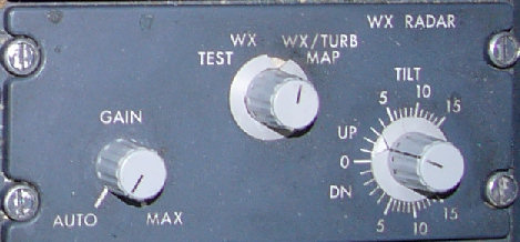 737 NG's are fitted with predictive windshear system (PWS). This is available below 2300ft. You do not need weather radar to be switched on for PWS to work, since it switches on automatically when take-off thrust is set. However there is a 12 sec warm up period, so if you want PWS available for the take-off you should switch the weather radar on when you line up.  Windshear warning displayed on the ND. Notice the cone and range at which windshear is predicted. EGPWS - Peaks Display The Peaks display overlays EGPWS terrain information onto the EHSI. The
colour coding is similar to wx radar but with several densities of each
colour being used. The simplified key is: The Peaks display overlays EGPWS terrain information onto the EHSI. The
colour coding is similar to wx radar but with several densities of each
colour being used. The simplified key is:
EGPWS Limitations
|
||||||||||||||||||||||||||||||||||||||||||||||||||||||||||||||||||||||||||||||||||||||||||||||||||||||||||
The Proximity Switch Electronic Unit (PSEU) is a system that
communicates the position or state of system components eg flaps,
gear, doors, etc to other systems. The 737-NG's are fitted with a PSEU
which controls the following systems: Take-off and landing
configuration warnings, landing gear transfer valve, landing
gear
position indicating and warning, air/ground relays, airstairs &
door warnings and
speedbrake deployed warning. | ||||||||||||||||||||||||||||||||||||||||||||||||||||||||||||||||||||||||||||||||||||||||||||||||||||||||||
Wednesday 26 June 2013
WARNING SYSTEMS
POWERPLANT
History
The original choice of powerplant was the Pratt &
Whitney JT8D-1, but before the first order had been
finalised the JT8D-7 was used for commonality with the current 727. The
-7 was flat rated to develop the same thrust
(14,000lb.st) at higher ambient temperatures than the -1 and became the
standard powerplant for the -100. By the end of the -200 production the
JT8D-17R was up
to 17,400lb.st. thrust.
Auxiliary inlet doors were fitted to early JT8D's around the nose cowl. These
were spring loaded and opened automatically whenever the pressure differential between
inlet and external static pressures was high, ie slow speed, high thrust
conditions (takeoff) to give additional engine air and closed again as airspeed
increased causing inlet static pressure to rise.
 JT8D
Cutaway
JT8D
Cutaway
The sole powerplant for all 737's after the -200 is the
CFM-56. The core is produced by General Electric and is virtually identical to the
F101 as used in the Rockwell B-1. SNECMA produce the fan, IP compressor, LP
turbine, thrust reversers and all external accessories. The name "CFM" comes
from GE's commercial engine designation "CF" and SNECMA's "M" for Moteurs.

One problem with such a
high bypass engine was its physical size and ground clearance; this was overcome by
mounting the accessories on the lower sides to flatten the nacelle bottom and
intake lip to give the "hamster pouch" look. The engines were moved
forward and raised, level with the upper surface of the wing and tilted 5
degrees up which not only helped the ground clearance but also directed the
exhaust downwards which reduced the effects of pylon overheating and gave some
vectored thrust to assist take-off performance. The CFM56-3 proved to be almost
20% more efficient than the JT8D.
The NG's use the CFM56-7B which has a 61 inch diameter
solid titanium wide-chord fan, new LP turbine turbomachinery, FADEC, and new single crystal material in the HP
turbine. All of which give an 8% fuel reduction, 15% maintenance cost reduction
and greater EGT margin compared to the CFM56-3.
One of the most significant improvements in the powerplant has been to the
noise levels. The original JT8D-9 engines in 1967 produced 75 decibel levels,
enough to disrupt normal conversation indoors, within a noise contour that
extended 12 miles along the take-off flight path. Since 1997 with the
introduction of the 737-700’s CFM56-7B engines, the 75-decibel noise contour is
now only 3.5 miles long.
The core engine (N2) is governed by
metering fuel (see
below), whereas the fan (N1) is a free turbine. The advantages of this include:
minimised inter-stage bleeding, fewer stalls or surges and an increased
compression ratio without decreasing efficiency.
This quote from CFMI in 1997:
"Since entering service in 1984, the CFM56-3 has established itself as the standard against which all other engines are judged in terms of reliability, durability, and cost of ownership. The fleet of nearly 1,800 CFM56-3-powered 737s in service worldwide have logged more than 61 million hours and 44 million cycles while maintaining a 99.98 percent dispatch reliability rate (one flight delayed or cancelled for engine-caused reasons per 5,000 departures), a .070 shop visit rate (one unscheduled shop visit per 14,286 flight hours), and an in-flight shutdown rate of .003 (one incident per 333,333 hours)."In 2012 a CFM56-7B engine delivered in 1999, powering a 737-800 aircraft, became the first engine in the world to achieve 50,000 hours without a shop visit.
"Tech Insertion" is an upgrade to the CFM56-5B & 7B available from early 2007. The package includes improvements to the HP
compressor, combustor and HP & LP turbines. The package give a longer
time on wing, about 5% lower maintenance costs, 15-20% lower oxides of nitrogen
(NOx) emissions, and 1% lower fuel burn.
Tech Insertion will become the new production configuration for both the
CFM56-7B and CFM56-5B. CFM is also defining potential upgrade kits that could be
made available to operators by late 2007.
CFM56-7BE "Evolution"
The new CFM56-7BE Product Improvement package announced in 2009 will have the following design changes & improvements:
- HPC outlet guide vane diffuser area ratio improved and pressure losses reduced.
- HPT blades numbers reduced, axial chord increased, tip geometry improved. Rotor redesigned.
- LPT blade & vane numbers reduced and profiles based on optimized loading distribution. LEAP56 incorporated.
- Primary nozzle, plug & strut faring all redesigned.
The -7BE will be able to be intermixed
with regular SAC/DAC or Tech Insertion engines subject to updated FMC,
MEDB and EEC. Entry into service is planned for mid-2011
From the press 2 Aug 2010:
CFM International has won certification for its
upgraded CFM56-7BE engine from the FAA and the European Aviation
Safety Agency (EASA), and is working with Boeing to prepare for flight
tests on a Boeing 737 starting in the fourth quarter of this year.
Entry into service is planned for mid-2011 to
coincide with 737 airframe improvements that, together with the engine
upgrade, are designed to provide a 2% improvement in fuel
consumption. CFM provisionally scheduled engine certification by the
end of the third quarter, but says development, including recently
completed flight tests, have progressed faster than expected.
Improvements include a new high-pressure compressor outlet guide vane
diffuser, high-pressure turbine blades, disks and forward outer seal.
The package also includes a new design of low-pressure turbine blades,
vanes and disk.
The first full CFM56-7BE type design engine
completed ground testing in January 2010, and overall completed 390
hours of ground testing, says the Franco-U.S. engine maker. In
addition, the upgraded CFM completed a 60-hour certification flight
test program in May on GE’s modified 747 flying testbed in
Victorville, Calif.
At the recent Farnborough International Airshow,
company officials said discussions are continuing with Airbus about a
possible upgrade for the CFM56-5B for the A320 family based on the
same technology suite. A decision on whether or not an upgraded
variant will be developed for Airbus will be finalized by year-end,
adds the engine maker.
Leap -1B
3 May 2013 - CFM has frozen the design of its next-generation Leap turbofan destined for Boeing’s 737 MAX family of narrowbodies.
The joint venture formed by General Electric (GE) and Snecma also has
started the assembly of the first of 28 Leap engines, which will be
used for ground and airborne tests between now and early 2015, when the
first variant of the new engine is due to be certified.
Gareth Richards, Leap’s program manager, during a May 2 press
conference in London said the design freeze on the Leap-1B variant was
completed on schedule on April 29. Design freeze of the -1A and -1C
variants of the engine, destined for the Airbus A320NEO and the Comac
C919, respectively, was completed in mid-2012.
Richards said the design freeze was a significant phase in the -1B’s
development and will allow engineers to begin producing parts by the end
of the year.
The schedule for the -1B is significantly different from the other
variants. The -1A and -1C, which differ only in aircraft integration and
fitting, are due to be tested in September, with certification due in
2015. For the -1B, the first engine will be ready for tests in June
2014, with certification due in 2016. According to CFM, the scheduling
differences were requested by Boeing.
CFM is working to increase production capacity for the engines and
supplier Albany Engineered Composites has opened a new plant in
Rochester, N.H., to build the composite main fan blades to be used in
the engine. A second facility in France will follow later this year.
CFM will build around 1,500 CFM56 engines in 2013, but expects Leap
production to increase to 1,700 engines a year by 2020. This would
require production of 36,000 fan blades each year.
Production of the CFM56 should begin to fall before then and will
probably cross over with the Leap engine for about three years through
to 2019. The only CFM56 production after that would be for spare
engines.
The -1C will be the first Leap to fly on GE’s Boeing 747 flying
testbed at the end of April 2014. The C919 first flight is expected
shortly after that, followed by U.S. engine certification at the end of
March 2015 and entry-into-service in the second quarter of 2016
Fuel
Thrust (fuel flow) is controlled primarily by a
hydro-mechanical MEC in response to thrust lever movement, as fitted to the
original 737-1/200’s. In the –3/4/500 series, fuel flow is further refined
electronically by the PMC, which acts without thrust lever movement. The 737-NG
models go one stage further with FADEC (EEC).
The 3/4/500's may be flown with PMC’s
inoperative, but an RTOW penalty (ie N1 reduction) is imposed because the N1
section will increase by approximately 4% during take-off due to windmilling
effects (FOTB 737-1, Jan 1985). This reduction should save reaching any engine
limits. The thrust levers should not be re-adjusted during the take-off after
thrust is set unless a red-line limit is likely to be exceeded, ie you should
allow the N1's to windmill up.
Fuel is heated to avoid icing by the returning oil in the MEC.
Oil
Oil pressure is measured before the bearings, where you
need it; oil temperature on return, at its hottest; and oil quantity at the
tank, which drops after engine start. Oil pressure is unregulated, therefore the
yellow band (13-26psi) is only valid at take-off thrust whereas the lower red
line (13psi) is valid at all times. If the oil pressure is ever at or below the
red line, the LOW OIL PRESSURE light will illuminate and that engine should be
shut down. NB on the 737-1/200 when the oil quantity gauge reads zero, there
could still be up to 5 quarts present.
Ignition
There are two independent AC ignition systems, L & R.
Starting with R selected on the first flight of the day provides a check of the
AC standby bus, which would be your only electrical source with the loss of
thrust on both engines and no APU. Normally, in-flight, no igniters are in use
as the combustion is self-sustaining. During engine start or take-off &
landing, GND & CONT use the selected igniters. In conditions of moderate or
severe precipitation, turbulence or icing, or for an in-flight relight, FLT
should be selected to use both igniters. NG aircraft: for in-flight engine
starts, GRD arms both igniters.
The 737-NG's allow the EEC to switch the ignition ON or OFF under certain
conditions:
- ON: For flameout protection. The EEC will automatically switch on both ignition systems if a flameout is detected.
- OFF: For ground start protection. The EEC will automatically switch off both ignition systems if a hot or wet start is detected.
Note that older 737-200s have ignition switch positions
named GRD, OFF, L IGN,
R IGN and FLT
while newer 737s use GRD, OFF, CONT and FLT. This is why QRH uses "ON"
(eg
in the One Engine Inop Landing checklist) to cover both LOW IGN &
CONT for operators with mixed fleets consisting of old and new
versions of the 737.

737-200 Ignition panel
Engine StartingMin duct pressure for start (Classics only): 30psi at msl, -½psi per 1000ft pressure altitude. Max: 48psi.Min 25% N2 (or 20% N2 at max motoring) to introduce fuel; any sooner could result in a hot start. Max motoring is when N2 does not increase by more than 1% in 5 seconds. Aborted engine start criteria:
Starter cutout is approx 46% N2 -3/4/500; 56% N2 -NG's. Starter duty cycle is:
During cold weather starts, oil pressure may temporary exceed the green band or may not show any increase until oil temperature rises. No indication of oil pressure by the time idle RPM is achieved requires an immediate engine shutdown. At low ambient temperatures, a temporary high oil pressure above the green band may be tolerated. When starting the engines in tailwind conditions, Boeing recommends making a normal start. Expect a longer cranking time to ensure N1 is rotating in the correct direction before moving the start lever. A higher than normal EGT should be expected, yet the same limits and procedures should apply.  Upper DU 
Lower DU 
Upper DU in Compact Display mode The Compact Display mode can only be shown when the MFD ENG button is pressed for the first time after the aircraft has been completely shut down. The photo shows this display with one engine started and nicely illustrates the blank parameters which are controlled by the EEC and hence are only displayed when the EEC powers up when the associated start switch is selected to GND. During start-up the EEC's receive electrical power from the AC transfer busses, but their normal source of power are their own alternators which cut-in when N2 is above 15%. |
 -200Adv
Engine Instruments
-200Adv
Engine Instruments |
 |
|
 3/4/500 EIS
 |
|
 NG EIS
 |
EIS Display
The introduction of Engine Instrument System (EIS) in late 1988 gave many
advantages over the electromechanical instruments present since 1967. ie a 10lb
weight reduction, improved reliability, reduction in power consumption,
detection of impending abnormal starts, storage of exceedances and a Built In
Test Equipment (BITE) check facility.
The BITE check is accessed by pressing a small recessed button at the bottom
of each eis panel, this is only possible when both engines N1 are below 10%.
Pressing these buttons will show an LED check during which the various checks
are conducted. If any of the checks fail, the appropriate code will be shown in
place of the affected parameters readout. The following codes are used:

| Primary EIS BITE Codes | |
| Code | Fault |
| ROM | Read Only Memory check |
| RAM | Random Access Memory check |
| FDC | Frequency to Digital Converter check |
| ENG | Engine Identity Inputs (not fuel flow) |
| PWR | Power Monitor |
| MMF | Maint Module Fault (fuel flow only) |
| RTC | Real Time Clock (fuel flow only) |
| ERF | Exceedance RAM Full (fuel flow only) |
| A/D | Analogue to Digital Converter (fuel flow only) |
| ARF | ARINC Receiver Fault (fuel flow only) |
| uP | Microprocessor |
Any exceedance of either N1, N2 or EGT is recorded at 1 sec intervals in a
non-volatile memory along with the fuel flow at the time, this data can be
downloaded by connecting an ARINC 429 bus reader. Up to 10 minutes of data can
be stored. The last exceedance is also put into volatile memory and can be read
straight from the EIS before aircraft electrical power is removed. This is done
by pressing the primary EIS BITE button twice within 2 seconds, this will then
alternately display the highest reading and the duration of the exceedance in
seconds.
| Secondary EIS BITE Codes | |
| Code | Fault |
| 0- | Microprocessor |
| 1- | Program Memory |
| 2- | Random Access Memory check |
| 3- | Analogue to Digital Converter |
| 4- | Power Monitor |
| 5- | 400Hz Reference Voltage |
| 6- | ARINC Receiver Fault |
Airborne Vibration Monitors (AVM)
All series of 737 have the facility for AVM although not all 737-200's have
them fitted. The early 737-1/200's had two vibration pickup points; One at the
turbine section and one at the engine inlet there was a selector switch so that
the crew could choose which to monitor. Some even had a high and low frequency
filter selection switch.
From Boeing Flt Ops Review, Feb 2003: "On airplanes with AVM procedures,
flight crews should also be made aware that AVM indications are not valid while
at takeoff power settings, during power changes, or until after engine thermal
stabilization. High AVM indications can also be observed during operations in
icing conditions."
High Pressure Turbine Clearance Control
The HPTCC system uses HP compressor bleed air to obtain maximum steady state
HPT performance and to minimise EGT transient overshoot during rapid change of
engine speed.
Variable Stator Vanes
The VSV actuation system controls primary airflow through the HP compressor
by varying the angle of the inlet guide vanes and three stages of variable
stator vanes.
Variable Bleed Valves
Control airflow quantity to the HP compressor. They are fully open during
rapid accelerations and reverse thrust operation.
Dual Annular Combustors (DAC)
The CFM56-7B is available with an optional DAC system, known as the
CFM56-7B/2, which considerably
reduces NOx emissions. DAC have 20 double tip
fuel nozzles instead of the single tip and a dual annular shaped combustion
chamber. The number of nozzles in use: 20/0, 20/10 or 20/20, varies depending
upon thrust required. The precise N1 ranges of the different modes varies with
ambient conditions.
- 20/20 mode - High power (cruise N1 and above)
- 20/10 mode - Medium power
- 20/00 mode - Low power (Idle N1)
This gives a lean fuel/air mixture, which reduces flame temperatures, and
also gives higher throughput velocities which reduce the residence time available
to form NOx. The net result is up to 40% less
NOx emissions than a standard CFM56-7.
The first were installed on the 737-600 fleet of SAS but unfortunately were
subject to resonance in the LPT-1 blades during operation in the 20/10 mode,
which occurred in an N1 range usually used during descent and approach. Although
there were no in-flight shutdowns, boroscope inspections revealed that the LPT
blades were starting to separate. CFM quickly replaced all blades on all DAC
engines with reinforced blades and have since replaced them again with a new
redesigned blade.
Reverse Thrust
 The original 737-1/200 thrust reversers were pneumatically powered
clamshell
doors taken straight from the 727 (shown left). When reverse was selected,
13th stage bleed air was ported to a pneumatic actuator that rotated the
deflector doors and clamshell doors into position. Unfortunately they were relatively ineffective and
apparently tended to push the aircraft up off the runway when deployed. This
reduced the downforce on the main wheels thereby reducing the effectiveness of
the wheel brakes.
The original 737-1/200 thrust reversers were pneumatically powered
clamshell
doors taken straight from the 727 (shown left). When reverse was selected,
13th stage bleed air was ported to a pneumatic actuator that rotated the
deflector doors and clamshell doors into position. Unfortunately they were relatively ineffective and
apparently tended to push the aircraft up off the runway when deployed. This
reduced the downforce on the main wheels thereby reducing the effectiveness of
the wheel brakes.
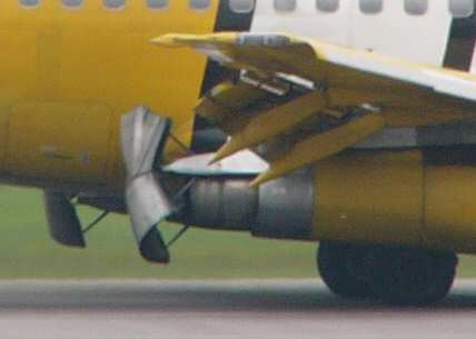
By 1969 these had been changed by Boeing and Rohr to the much more successful hydraulically powered
target type thrust reversers (shown right). This required a 48 inch
extension to the tailpipe to accommodate the two cylindrical deflector doors
which were mounted on a four bar linkage system and associated hydraulics. The
doors are set 35 degrees away from the vertical to allow the exhaust to be
deflected inboard and over the wings and outboard and under the wings. This
ensures that exhaust and debris is not blown into the wheel-well, nor is it
blown directly downwards which would lift the weight off the wheels or be
re-ingested. Fortunately the new longer nacelle improved cruise performance by
improving internal airflow within the engine and also reduced cruise drag. These
thrust reversers are locked against inadvertent deployment by both deflector
door locks and the four bar linkage being overcenter. To illustrate how poor the
original clamshell system was, Boeings own data says target type thrust
reversers at 1.5 EPR are twice as effective as clamshells at full thrust!
 The CFM56 uses blocker doors and cascade vanes to direct fan air
forwards. Net reverse thrust is defined as: fan reverser air, minus forward
thrust from engine core, plus form drag from the blocker door. As this is
significantly greater at higher thrust, reverse thrust should be used
immediately after landing or RTO and, if conditions allow, should be reduced to
idle by 60kts to avoid debris ingestion damage. Caution: It is possible to deploy reverse thrust
when either Rad Alt is below 10ft – this is not recommended.
The CFM56 uses blocker doors and cascade vanes to direct fan air
forwards. Net reverse thrust is defined as: fan reverser air, minus forward
thrust from engine core, plus form drag from the blocker door. As this is
significantly greater at higher thrust, reverse thrust should be used
immediately after landing or RTO and, if conditions allow, should be reduced to
idle by 60kts to avoid debris ingestion damage. Caution: It is possible to deploy reverse thrust
when either Rad Alt is below 10ft – this is not recommended.
The REVERSER light shows either control valve or sleeve
position disagreement or that the auto-restow circuit is activated. This light
will illuminate every time the reverser is commanded to stow, but extinguishes
after the stow has completed, and will only bring up master caution ENG if a
malfunction has occurred. Recycling the reverse thrust will often clear the
fault. If this occurs in-flight, reverse thrust will be available after landing.
The REVERSER UNLOCKED light (EIS panel) is potentially much more
serious and will illuminate in-flight if a sleeve has mechanically unlocked.
Follow the QRH drill, but only multiple failures will allow the engine to go
into reverse thrust.

The 737-1/200 thrust reverser panel has a LOW PRESSURE light which refers to
the reverser accumulator pressure when insufficient pressure is available to
deploy the reversers. The blue caption between the switches is ISOLATION VALVE
and illuminates when the three conditions for reverse thrust are satisfied:
Engine running, Aircraft on ground & Fire switches in normal position. The
guarded NORMAL / OVERRIDE switches to enable the reverse thrust to be selected
on the ground with the engines stopped (for maintenance purposes).

The first "hushkit" was not visible externally, in 1982 exhaust mixers were
made available for the JT8D-15, -17 or -17R. These were fitted behind the LP
turbine to mix the hot gas core airflow with the cooler bypassed fan air. This
increased mixing reduced noise levels by up to 3.6 EPNdB.
Several different Stage III hushkits
have been available from
manufacturers Nordam (shown right) and AvAero since 1992. The Nordam comes in HGW and
LGW versions.
As hushkits use more fuel, the EU tried to ban all hushkitted aircraft flying
into the EU from April 2002. This was strongly opposed and the directive has
been changed to allow hushkitted aircraft to use airports which will accept
them.
737 classics may be fitted with hardwall forward acoustic panels which reduce
noise by 1 EPNdB
Additional References
- Jet Engine Malfunctions and Responses
- Powerplant Tech Quiz
- Assumed temperature thrust reduction
- CFM 56-3 Specific Operating Instructions - Notes from the engine operating manual.
- Part 1: Engine & APU specs, troubleshooting & maintenance tips.
- JT8D-15A: Study notes.
- Birdstrike Damage: Photos & comments.
Limitations
| Series | 1/200 | 3/4/500 | 6/7/8/900/BBJ |
| Engine | JT8-17A | CFM56-3 | CFM56-7 |
|
Max time limit for take-off or go-around thrust: |
5 mins | 5 mins * | 5 mins * |
|
Max N1 |
102.4% | 106% | 104% |
|
Max N2 |
100% | 105% | 105% |
|
Max EGT's: |
|||
|
Take-off (5 min limit) |
650°C | 930°C | 950°C |
|
Continuous |
610°C | 895°C | 925°C |
|
Start |
575°C | 725°C | 725°C |
|
Oil T's & P's |
|||
|
Max temperature |
165°C | 165°C | 155°C |
|
15 minute limit (45 minute limit on NG) |
130-165°C | 160-165°C | 140-155°C |
|
Max continuous |
130°C | 160°C | 140°C |
|
Min oil press |
40psi |
13psi (warning light), 26psi (gauge) |
13psi (warning light), 26psi (gauge) |
|
Min oil quantity (at dispatch) |
2.25 USG |
60% full (12 US Quarts) ** |
60% full (12 US Quarts) ** |
| Starting pressures prior to starter engagement |
30psi -1/2psi per
1000' amsl
|
N/A | |
| Starter duty cycle |
1st attempt: 2min on, 20sec off 2nd & subsequent attempt: 2min on, 3min off |
2mins on, 10secs off. | |
| * May be increased to 10 mins if certified ** See AMM Task 12-13-11-600-801 | |||
Engine Ratings
Maximum Certified Thrust - This is the maximum
thrust certified during testing for each series of 737. This is also the
thrust that you get when you firewall the thrust levers, regardless of
the maximum rated thrust.
On the 737NG, the EEC limits the
maximum certified thrust gained from data in the engine strut according to the airplane model as follows:
| Aircraft Series | Maximum Certified Thrust |
| 737-600 | CFM56-7B22 = 22,700lb.st |
| 737-700 | CFM56-7B24 = 24,200lb.st |
| 737-800 | CFM56-7B27 = 27,300lb.st |
| 737-900 | CFM56-7B27 = 27,300lb.st |
Maximum Rated Thrust - This is the maximum thrust
for the installed engine that the autothrottle will command. This is
specified by the operator from the options in the table below.
| Engine | Aircraft Series | Max Static Thrust (lb.st.) | Bypass Ratio | EGT Margin (C) |
| JT8D-7/7A/7B | 1/200 | 14,000 | 1.10 | |
| JT8D-9/9A | 1/200 | 14,500 | 1.04 | |
| JT8D-15/15A | 200Adv | 15,500 | 0.99 | |
| JT8D-17/17A | 200Adv | 16,000 | 1.02 | |
| JT8D-17R | 200Adv | 17,400 | 1.00 | |
| CFM56-3B4 | 500 | 18,500 | 5.0 | 90 |
| CFM56-3B1 | 3/500 | 20,000 | 5.0 | 70 |
| CFM56-3B2 | 3/400 | 22,000 | 5.0 | 50 |
| CFM56-3C1 | 400 | 23,500 | 4.9 | 45 |
| CFM56-7B18 | 600 | 19,500 | 5.5 | 145 |
| CFM56-7B20 | 6/700 | 20,600 | 5.4 | 148 |
| CFM56-7B22 | 6/700 | 22,700 | 5.3 | 150 |
| CFM56-7B24 | 7/8/900 | 24,200 | 5.3 | 125 |
| CFM56-7B26 | 7/8/900/BBJ | 26,400 | 5.1 | 85 |
| CFM56-7B27 | 8/900/BBJ | 27,300 | 5.0 | ? |
Misc Photos
 |
The left hand side of the CFM56-3. The large silver coloured pipe is the start air manifold with the starter located at its base. The black unit below that is the CSD. The green unit forward (left) of the CSD is the generator cooling air collector shroud, the silver-gold thing forward of that (with the wire bundle visible) is the generator, and the green cap most forward is the generator cooling air inlet. |
 |
The view into the JT8D jetpipe.
The corrugated ring is the mixer unit, this is designed to thoroughly
mix the bypass air with the turbine exhaust. The exhaust cone makes a divergent flow which slows down the exhaust and also protects the rear face of the last turbine stage. |
 |
The view into the CFM56-3 jetpipe. This is the turbine exhaust area, no mixing is required as the bypass air is exhausted coaxially. |
 |
There are two fan inlet temperature sensors in the CFM56-3 engine intake. The one at the 2 o'clock position is used by the PMC and the one at the 11 o'clock position is used by the MEC. The MEC uses the signal to establish parameters to control low and high idle power schedules.The temperature data is used for thrust management and variable bleed valves, variable stator vanes & high / low pressure turbine clearance control systems. |
 |
The CFM56-7 inlet has just one
fan inlet temperature
probe, which is for the EEC (because there is no PMC on the NG's).A
subtle difference between the NG & classic temp probes is that the NG's
only use inlet temp data on the ground and for 5 minutes after take-off.
In-flight after 5 minutes temp data is taken from the ADIRU's. The temperature data is used for thrust management and variable bleed valves, variable stator vanes & high / low pressure turbine clearance control systems. |
 |
The CFM56-7 spinner has a unique conelliptical profile. The first 737-3/400's had a conical (sharp pointed) spinner but these tended to shed ice into the core. This was one of the reasons for the early limitation of minimum 45% N1 in icing conditions which made descent management quite difficult. They were later replaced with elliptical (round nosed) spinners which succeeded in deflecting the ice away from the core, but because of their larger stagnation point, were more prone to picking up ice in the first place. The conelliptical spinner of the NG's neatly solves both problems. |
 |
The CFM56-7 tailpipe is slightly longer then the CFM56-3 and has a small tube protruding from the faring. This is the Aft Fairing Drain Tube for any hydraulic fluid, oil or fuel that may collect in there. There is also a second drain tube that does not protrude located on the inside of the fairing. |
 |
The JT8D tailpipe fitted as standard from l/n 135 onwards. The original thrust reversers were totally redesigned by Boeing and Rohr since the aircraft had inherited the same internal pneumatically powered clamshell thrust reversers as the 727 which were relatively ineffective and apparently tended to lift the aircraft off the runway when deployed! The redesign to external hydraulically powered target reversers cost Boeing $24 million but dramatically improved its short field performance which boosted sales to carriers proposing to use the aircraft as a regional jet from short runways. Also the engine nacelles were extended by 1.14m as a drag reduction measure. |
 |
The outboard side of the JT8D-9A with the cowling open. |
PNEUMATICS

737-3/500 Pneumatics Panel
|
General
The
pneumatic system can be supplied by engines, APU or a ground source. The
manifold is normally split by the isolation valve. With the isolation valve
switch in AUTO, the isolation valve will only open when an engine bleed air or
pack switch is selected OFF.
Air for engine starting, air conditioning packs, wing
anti-ice and the hydraulic reservoirs comes from their respective ducts.
Air for pressurisation of the water tank and the aspirated TAT probe
come from the left
pneumatic duct. External air for engine starting feeds into the right pneumatic
duct. Ground conditioned air feeds directly into the mix manifold.
The minimum pneumatic duct pressure (with anti-ice
off) for normal operation is 18psi.
If engine bleed air temperature or pressure exceed limits,
the BLEED TRIP OFF light will illuminate and the bleed valve will close. You may
use the TRIP RESET switch after a short cooling period. If the BLEED TRIP OFF
light does not extinguish, it may be due to an overpressure condition.
Bleed trip off's are most common on full thrust, bleeds off, take-off's.
The reason is excessive leakage past the closed hi stage valve butterfly
which leads to a pressure build up at the downstream port on the
overpressure switch within the hi stage regulator. The simple in-flight
fix is to reduce duct pressure by selecting CLB-2 and/or using
engine and/or wing anti-ice.
WING-BODY OVERHEAT indicates a leak in the corresponding
bleed air duct. This is particularly serious if the leak is in the left hand
side, as this includes the ducting to the APU. The wing-body overheat circuits
may be tested by pressing the OVHT TEST switch; both wing-body overheat lights
should illuminate after a minimum of 5 seconds. This test is part of the daily
inspection.
|

737-400 Pneumatics Panel
|
Differences1/200's - The PACK switches are simply OFF/ON, rather than OFF/AUTO/HIGH on all other series.4/8/900's - Have two recirc fans for pax comfort and PACK warning lights instead of PACK TRIP OFF. See Air conditioning for an explanation. There are also two sidewall risers either side instead of one on all other series, this is why there appear to be two missing windows forward of the engine inlet. 
737-400 Sidewall risers
|
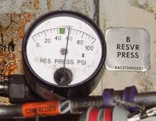 |
The hydraulic reservoirs are pressurised to ensure a positive flow of fluid reaches the pumps. A from the left manifold and B from the right. See wheel-well fwd. |
Schematic
Schematic courtesy of Derek Watts
|
|
Limitations
|
Max external air pressure: |
60 psig |
|
Max external air temp: |
450°F / 232°C |
| One pack may be inoperative provided maximum altitude is: | FL250 |
NAVIGATION
 |
Position The aircraft has several nav positions, many of which are in use simultaneously! They can all be seen on the POS REF page of the FMC. 
IRS L & IRS R Position: Each IRS
computes its own position independently; consequently they will diverge
slightly during the course of the flight. After the alignment process is complete, there is no
updating of either IRS positions from any external sources. Therefore it
is important to set the IRS position accurately in POS
INIT.
GPS L & GPS R Position: (NG only) The FMC uses GPS position
as first priority for FMC position updates. Note this allows the FMC to
position update accurately on the ground, eg if no stand position is
entered in POS INIT. This practically eliminates the need to enter a
take-off shift in the TAKE-OFF REF
page.
|
||||||||||||||||||||||||||||||||||||||||||||||||||||||||
 |
Radio Position: This is computed
automatically by the FMC. Best results are achieved with both Nav boxes
selected to AUTO (happens automatically on NG), thus allowing the FMC to select the optimum DME or VOR
stations required for the position fix. Series 500 aircraft have an
extra dedicated DME interogator (hidden) for this purpose and NG's have two. Radio
position is found from either a pair of DME stations that have the best
range and geometry or from DME/VOR or even DME/LOC.
The NAV STATUS page shows the current status of the navaids being tuned.
Navaids being used for navigation (ie radio position) are highlighted (here WTM & OTR). |
||||||||||||||||||||||||||||||||||||||||||||||||||||||||


|
FMC Position: FMC navigational computations & LNAV are based upon this.
The FMC uses GPS position (NG's only) as
first priority for FMC position updates, it will even position update on the
ground. If GPS is not available, FMC position is biased approximately 80:20 toward radio
position and IRS L. When radio updating is not available, an IRS NAV
ONLY message appears. The FMC will then use a “most probable”
position based on the IRS position error as found during previous
monitoring when a radio position was available. The FMC position should
be closely monitored if IRS NAV ONLY is in use for long periods.
The POS SHIFT page shows the bearing & distance of other systems
positions away from the FMC position. Use this page to force the FMC position to
any of those offered. RNP/ACTUAL Actual Navigation Performance (ANP) is the FMC's estimate of the quality of its position determination. The FMC is 95% certain the the aircraft's actual position lies within a circle of radius ANP centred on the FMC position. Therefore the lower the ANP, the more confident the FMC is of its position estimate. Required Navigation Performance (RNP) is the desired limit of navigational accuracy and is specified by the kind of airspace you are in. Eg for BRNAV above FL150, RNP=2.00nm. The RNP may be overwritten by crew. ACTUAL should always be less than RNP. |
||||||||||||||||||||||||||||||||||||||||||||||||||||||||
 |
If a navaid or GPS system is unreliable or giving invalid data then they can be inhibited using the NAV OPTIONS page. | ||||||||||||||||||||||||||||||||||||||||||||||||||||||||
|
There is an AFM limitation prohibiting use of LNAV when operating in QFE
airspace. This is because several ARINC 424 leg types used in FMC nav databases terminate
at MSL altitudes. If baro set is referenced to QFE, these legs will
sequence at the wrong time and can lead to navigational errors. EHSI & Navigation Display (ND) |
|||||||||||||||||||||||||||||||||||||||||||||||||||||||||
 737-3/4/500
EFIS
Control
Panel
737-3/4/500
EFIS
Control
Panel |
 737-NG
EFIS
Control
Panel
737-NG
EFIS
Control
Panel |
||||||||||||||||||||||||||||||||||||||||||||||||||||||||
| In the NG,
if an EFIS control panel fails, you will get a
DISPLAYS CONTROL PANEL annunciation on the ND. There is an
additional, rather bizarre, attention getter because the altimeter will
blank on the failed side, with an ALT flag, until the DISPLAYS - CONTROL
PANEL switch is positioned to the good side. Note that this is not the
same as the EFI switch on the -3/4/500's which was used to switch symbol
generators. |
|||||||||||||||||||||||||||||||||||||||||||||||||||||||||
 The -3/4/500 Electronic Horizontal Situation Indicator (Map mode)
 |
737-NG
Navigation
Display
(Map
mode) |
||||||||||||||||||||||||||||||||||||||||||||||||||||||||
 EHSI
-
Nav
EHSI
-
Nav |
 EHSI
-
Plan
EHSI
-
Plan |
||||||||||||||||||||||||||||||||||||||||||||||||||||||||
 EHSI
-
Full
VOR/ILS
EHSI
-
Full
VOR/ILS |
 EHSI
-
Expanded
VOR/ILS
EHSI
-
Expanded
VOR/ILS |
||||||||||||||||||||||||||||||||||||||||||||||||||||||||
 EHSI
-
Map
EHSI
-
Map |
 EHSI
-
Center
Map
EHSI
-
Center
Map |
||||||||||||||||||||||||||||||||||||||||||||||||||||||||
 ***
WARNING
***
***
WARNING
***
The
The ND DME readout below the VOR may not necessarily be that of the VOR which is displayed.
This photograph shows that Nav 1 has been manually tuned to
110.20 as shown in 1L of the FMC. DVL VOR identifier has been decoded by
the auto-ident facility so "DVL" is displayed in large characters both
on the FMC and the bottom left of the ND. Below this is displayed "DME
128" implying that this is the DME from DVL VOR. However it can be seen on the ND that the DVL VOR is only about 70nm ahead. In fact DVL is only a VOR station and it has no DME facility, the DME was from another station on 110.20. The second station could be identified aurally by the higher pitched tone as "LRH" but was not displaying as such in line 2L of the FMC. I only discovered this by chance as I happened to be following the aircraft progress by tuning beacons en-route (the way we used to do!). In my opinion, this illustrates the need to aurally identify any beacons, particularly DME, you may have to use, even if they are displayed as decoded. |
|||||||||||||||||||||||||||||||||||||||||||||||||||||||||
|
|
|||||||||||||||||||||||||||||||||||||||||||||||||||||||||
Instrument Transfer
If either
Nav receiver
fails, the VHF NAV
transfer switch may be used to display the functioning
Nav information onto
both EFIS and RDMI’s. With
Nav transferred, the MCP course selector on
the serviceable side becomes the master, but all other EFIS selections
remain independent.
If
an IRS
fails, the IRS transfer switch is
used to switch all associated systems to the functioning IRS.
|
1/200
|
||||||||||||||||||||||||||||||||||||||||||||||||||||||||
|
3/4/500
|
NG's
|
||||||||||||||||||||||||||||||||||||||||||||||||||||||||
IRS Malfunction Codes (Classics)
|
|||||||||||||||||||||||||||||||||||||||||||||||||||||||||
Alternate Navigation System - ANS (If installed)This is an option for the -3/4/500 series. ANS is an IRS based system which provides lateral navigation capability independent of the FMC. The ANS with the Control Display Units (AN/CDU) can be operated in parallel with the FMC for an independent cross-check of FMC/CDU operation. |
|||||||||||||||||||||||||||||||||||||||||||||||||||||||||
|
Navigation Mode Selectors
|
The ANS is two separate systems, ANS-L & ANS-R. Each consists of its own
AN/CDU and "on-side" IRS. Each pilot has his own navigation mode selector to specify the source of navigation information to his EFIS symbol generator and flight director. |
||||||||||||||||||||||||||||||||||||||||||||||||||||||||
 |
The ANS also performs computations related to lateral navigation which can provide LNAV commands to the AFDS in the event of an FMC failure. | ||||||||||||||||||||||||||||||||||||||||||||||||||||||||

|
The IRS PROGRESS page is similar to the normal PROGRESS page except that all data is from the "on-side" IRS (L in this example). | ||||||||||||||||||||||||||||||||||||||||||||||||||||||||
 AN/CDU Pages
 |
AN/CDU has no performance or navigation database. All waypoints must therefore be defined in terms of lat & long. The AN/CDU memory can only store 20 waypoints, these can be entered on the ground or in-flight and may be taken from FMC data using the CROSSLOAD function. | ||||||||||||||||||||||||||||||||||||||||||||||||||||||||
FutureIn Jan 2003, the 737 became available with three new flight-deck technologies: Vertical Situation Display (VSD), Navigation Performance Scales (NPS) and Integrated Approach Navigation (IAN).The Vertical Situation Display shows the current and predicted flight path of the airplane and indicates potential conflicts with terrain. Navigation Performance Scales NPS use vertical and horizontal indicators to provide precise position awareness on the primary flight displays to will allow the aircraft to navigate through a narrower flight path with higher accuracy. The Integrated Approach Navigation enhances current airplane landing approach capability by simplifying pilot procedures and potentially reducing the number of approach procedures pilots have learned in training. For more information about NPS and IAN see the section on Flight Instruments. |
|||||||||||||||||||||||||||||||||||||||||||||||||||||||||
 Vertical Situation Display
 |
Vertical
Situation
Display
The VSD, now certified on NG's, gives a graphical picture of the aircraft's vertical flight path. The aim to is reduce the number of CFIT accidents; profile related incidents, particularly on non-precision approaches and earlier recognition of unstabilised approaches. The VSD works with the Terrain Awareness and Warning System (TAWS) to display a vertical profile of the aircrafts predicted flight path (shown between the blue dashes) on the lower section of the ND. It is selected on with the DATA button on the EFIS control panel. VSD can be retrofitted into any NG but it requires software changes to the displays and FMC and also some additional hardware displays. Click here for presentation on VSD |
ETOPS
In 1953, the United States developed regulations that
prohibited two-engine airplanes from routes more than 60 min single-engine
flying time from an adequate airport (FAR 121.161). These regulations were
introduced based upon experience with the airliners of the time ie piston
engined aircraft, which were much less reliable than modern jet aircraft.
Nevertheless, the rule still stands.
ETOPS allows operators to deviate from this rule under
certain conditions. By incorporating specific hardware improvements and
establishing specific maintenance and operational procedures, operators can
fly extended distances up to 180 min from the alternate airport. These
hardware improvements were designed into Boeing 737-600/700/800/900.
The following table gives some FAA ETOPS approval times &
dates:
| Aircraft Series | Engine | ETOPS-120 approval date | ETOPS-180 approval date |
| 737-200 | JT8D -9/9A | Dec 1985 | |
| JT8D -15/15A | Dec 1986 | ||
| JT8D -17/17A | Dec 1986 | ||
| 737-300/400/500 | CFM56-3 | Sept 1990 | |
| 737-600/700/800/900 | CFM56-7 | Sept 1999 | |
| 737-BBJ1/BBJ2 | CFM56-7 | Sept 1999 |
Subscribe to:
Posts (Atom)